Slice Model
The slicing feature allows the user to divide the Composite Model into Z-Slices each of which will become a Component. This is for customers who need to cut a part which exceeds the Z depth of their machine gantry, the cutting length of their tools or the thickness of the material they are using. Once the slices have been cut on the CNC then they can be re-assembled to make the finished full depth part.
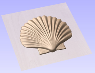
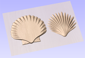
When this function is executed each slice will become a Component in the Component Tree and can then be moved into position and have toolpaths calculated on it. An example of this is shown in the images below, on the left it shows a scallop shell component that is 3 inches thick, the image below right shows this divided into two separate components, each a 1.5 inch slice of the original.
Note
Before using the Slice model command it is important to make sure that you hide any components that you do not wish to include in the operation.
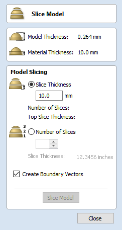
When the icon is clicked the Slice Model form will appear. This can be used to control the number and thickness of slices which will be created. At the top of the form it will display some reference information showing the thickness of the current Composite Model and also the currently defined Material Thickness (for machining).
 Model Slicing
Slice Thickness
Checking ✓ this option will let you define a particular value for each slice. Right below this the Number of Slices will be displayed which is determined by the Composite Model thickness divided by the Slice Thickness. The model will be sliced from the bottom up and if the Composite Model thickness does not divide exactly by the Slice Thickness then the top slice may not be a whole number. To help indicate how the part is going to be divided the Top Slice Thickness is displayed in the form.
Example
If the Composite Model is 4.75 inches thick and you define a Slice Thickness of 2 inches then the software will create 3 Component slices - the bottom and middle slice will both be 2 inches thick and the top slice will be 0.75 inches thick.
Number of Slices
Checking ✓ this option will divide the model into a specific number of slices. The slice thickness will be determined by the Composite Model thickness divided by the Number of Slices defined. This may be a good option to use if the specific slice thickness is not important (for instance if it does not relate to material thickness).
Example
If the Composite Model is 3.96 inches thick and you define 3 Slices then the software will create 3 Component slices each 1.32 inches thick.
Create Boundary Vectors
Checking ✓ this option will cause the slicer to create vector boundaries for each slice. These can be useful for defining the subsequent machining regions required to cut each part. The boundary vectors will be placed on the same layer in the 2D View as the component preview for their associated model slice.
Slice Model
Clicking will apply the choices made in the form and create the Components which represent each slice of the Composite Model.
Note
The Component Tree will retain a copy of the original Components in the part as well as the new Slice Components. This may result in a very thick looking model as all the slices will be added to the original shapes. At this point you can delete, undraw or move Components before proceeding with any additional operations.
Close
Clicking will close the Slice Model form without completing the operation.